

Warm welcome friends to our #LearnMSBIstepbystep site, Here you will get all resources related to Microsoft Business Intelligence like videos, articles e-books and so on. We not only have these self-learning materials on MSBI but we do also have in other topic like Learn C# in 100 hours, Sharepoint, AngularJS, ASP.NET, SQL Server and so on.
I'm Gurunatha Dogi a faculty, a technical writer @Questpond, Questpond is an Information Technology step by step schools covers all technical topics like .NET, C#, AngularJS, Java, MSBI, ASP.NET, MCV5 and many more. For more information visit our price page.
All the videos recorded and other self learning materials made by Microsoft MVP Mr.ShivPrasad Koirala having more than 20 years of experience. To know more about him just type his name on google search and know more about him.
Now, let's come back to our article, In this article we will understand how to design snowflake schema in SSIS with a real time example. This is connected article of previous two article so kindly visit articles section to read other two articles. There we have explained theory or defination part of Snowflake schema along differences with star schema.
SnowFlake Schema where few dimension tables are connected to each other and some are connected to fact table. So let's design it in a same way step by step.
Real Time example : We will take up same example which we saw in our previous article on designing star schema i.e. Customer is buying a property, i.e. we will have four dimension table Property, PropertySubType, State and City and one fact table (Customer Table). Here State table will be connected to city since India we all knows that a State can have multiple cities. and same way Property will be connected to PropertySubtype coz Property is divided into Residential and Commercial and Residential can have their PropertySubTypes like Flat, Villas, Bunglows Apartment etc. So summarizing State -> connected to -> City and Property -> connected to -> PropertySubType. Further City -> connected to Fact Table and PropertySubType -> connected to Fact Table
Before start reading this article further kindly have a look on our previous articles on Designing Star Schema and Theory understanding of Dimension Table FactTable Star Schema SnowFlake because both articles and this current article is related to each other.
Step 1 :
In this step we will create four dimension tables in SQL Server using SQL Mgt Studio as shown in below image. All these steps are same which we already did in our previous article.
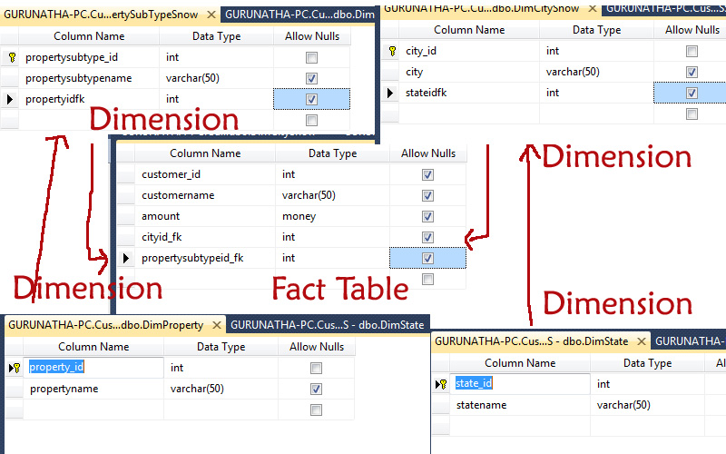
So guys you have seen that we have successfully created all dimension datatables and 1 fact table.
Step 2 :
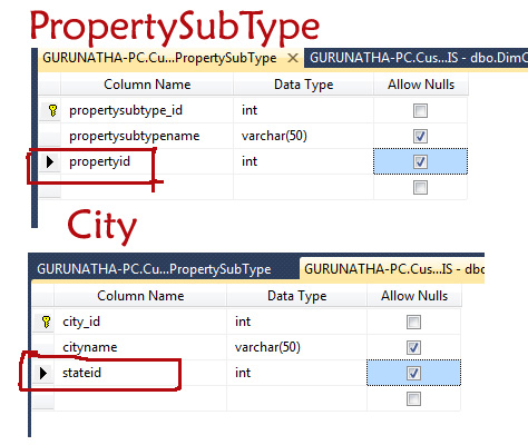
In this step we will create foreign key for state_id and property_id in City master table and PropertySubType master table respectively. Image representation is shown below. This is because we want to connect State master and City master, Property master and PropertySubType master via primary-foreign key relationship./p>
Step 3 :
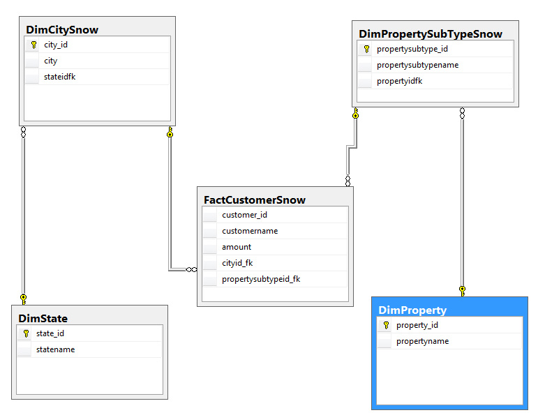
This is very important step for making relationship between tables or to connect tables each other via primary-foreign key relationship. We will use Sql server database diagram to create relationship between tables.
Here we will connect State master and City master, Property master and PropertySubType master, City master and Fact Customer table, PropertySubType master and Fact Customer table. Representation is shown below.
Step 3 :
In this step we will create our source files for our respective datawarehouse i.e. State, City, Property, PropertySubType and Customer.
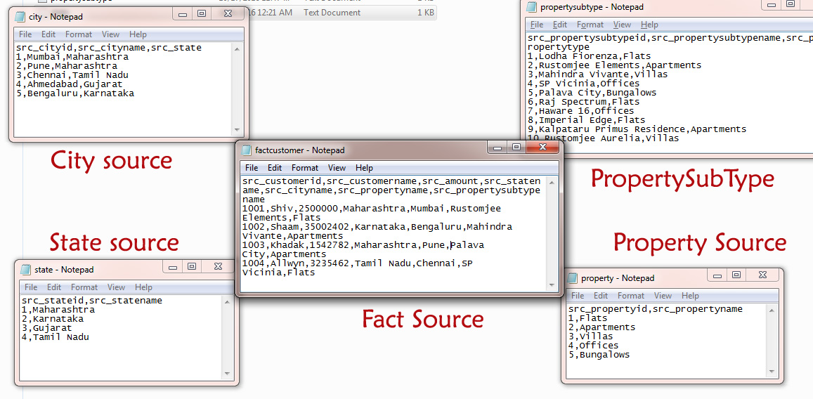
If you see closely our source data of City is not matching with destination City master table. Here we have state in a string type but in our destination we need stateidfk in a INT format due to this we need to load State master first and then City master and while loading city master we will do lookup to get stateidfk as foreign key then same load it city master table. Same applicable for PropertySubtype master and fact Customer table master.
Data loading goes in this way State -> City, Property -> PropertySubType, City -> Customer fact table, PropertySubType -> Fact Customer Table in a snowflake schema model. Snowflake schema model where not all but few dimension tables are connected to fact table and rest few are connected to each other.
Step 4 :
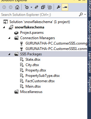
After completing 3 steps let's start designing our snowflake schema structure in BI visual studio, so open that and create a new integration service project (SSIS project). As we discussed earlier our loading source file structure same way we will load it. So let's different packages for all dimension table and 1 fact table i.e. State, City, Property and PropertySubType and Customer.
Why we are doing this is because we want to load data or run package one by one so if we create different package for all it becomes easy to manage and execute the project. We will also create one main package to run all these packages under one roof.
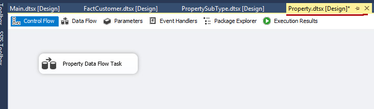
So let's create with State.dtsx package as shown in below image.
Same way we will create different packages as shown in below image.
Step 5 :
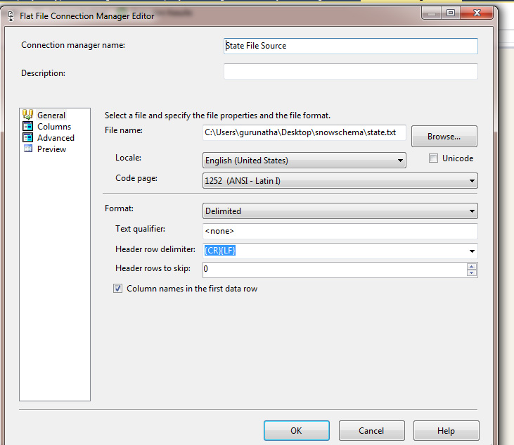
So let's start with state package, open state package and dragdrop data flow task in control flow task -> go to data flow task and since our data is in a CSV format we will dragdrop Flat File Source from SSIS toolbox.
Configure Flat File source for state source data as shown in below image.
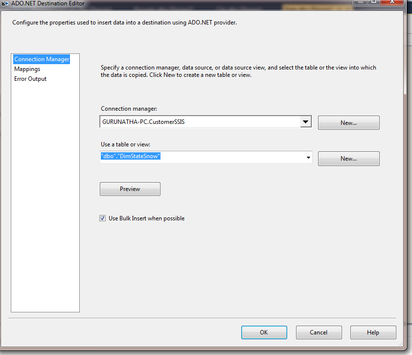
Now let's drag n drop ADO.NET destination component from SSIS toolbox and configure it to save data in State master table as shown in below image.
If you dont no steps properly then read this article Here we have explained properly each step and same need to follow here too.
So friends once you have completed with State.dtsx package now same way create it for Property package. This is kind of test for practice. So create property package using above steps.
Step 6 :
Here in this step we will load city data from source file, since at our source end state is in string format and in the destination (city master) we need stateidfk as foreign key for that we need to do lookup. lookup is a SSIS component which matches string and get macthed row primary id. So here using lookup component we can match city source statename with destination state master table and get stateidfk.
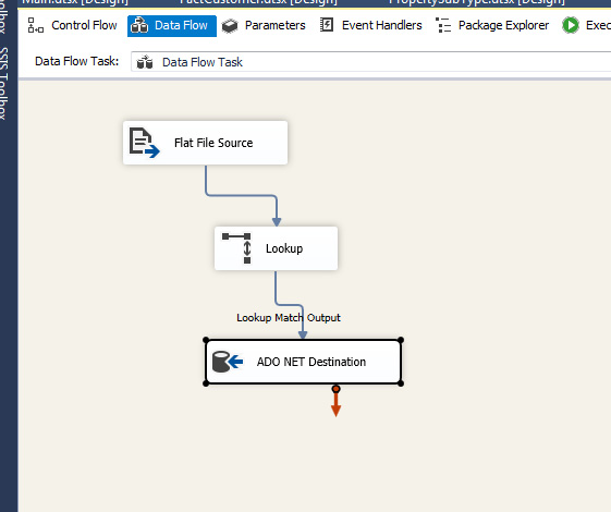
Open city.dtsx package and drag n drop data flow task -> go to data flow tab and drag n drop Flat File Source.
Configure Flat File source and now drag n drop lookup component and attach with Flat File source as shown in below image.
Right click on lookup and configure it, Connection should be OLEDB connection to select state datatable. Now go to columns menu here you will get both table views just drag and drop arrow from source state to state datatable state. column and just check on checkbox of state_id primary key of datatable as shown in below image.
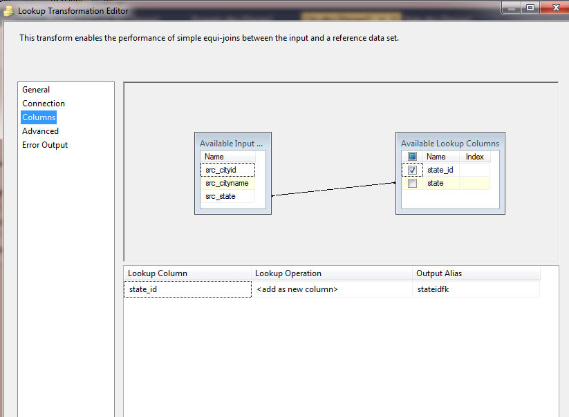
So click on OK button to save it.
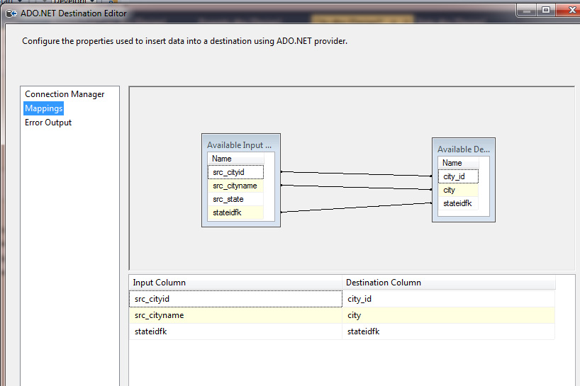
Now drag n drop ADO.NET destination component and configure it. If you see in the column mapping you will find a new added column to the list is stateidfk as shown in below image.
Step 7 :
The way we have configured city.dtsx package same way as a test practical do it for PropertySubType.dtsx package repeat same steps.
Step 8 :
Now we need to configure fact-table package i.e. Customer Table.
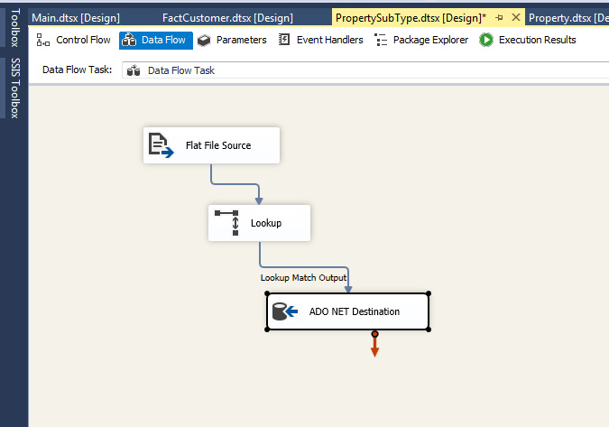
Drag and drop -> flat file source and configure fact source file. Since we need to get foreign keys in our fact-destination columns i.e. for city and propertysubtype. We will do lookup and use same steps as we did it above.
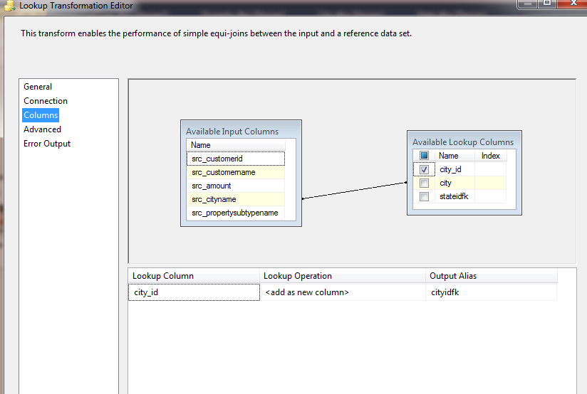
There will be separate two lookup components for each city and propertysubtype so let's first drag and drop lookup for city and configure it.
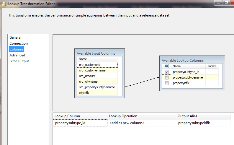
Now drag and drop one more lookup component for PropertySubtype and configure it as shown in below image.
So hey friends, since we have both foreign keyps of cityidfk and propertysubtypeidfk so let's load this data in a destination fact-table.
Use ADO.NET destination component and configure component as match the columns as shown in below image.
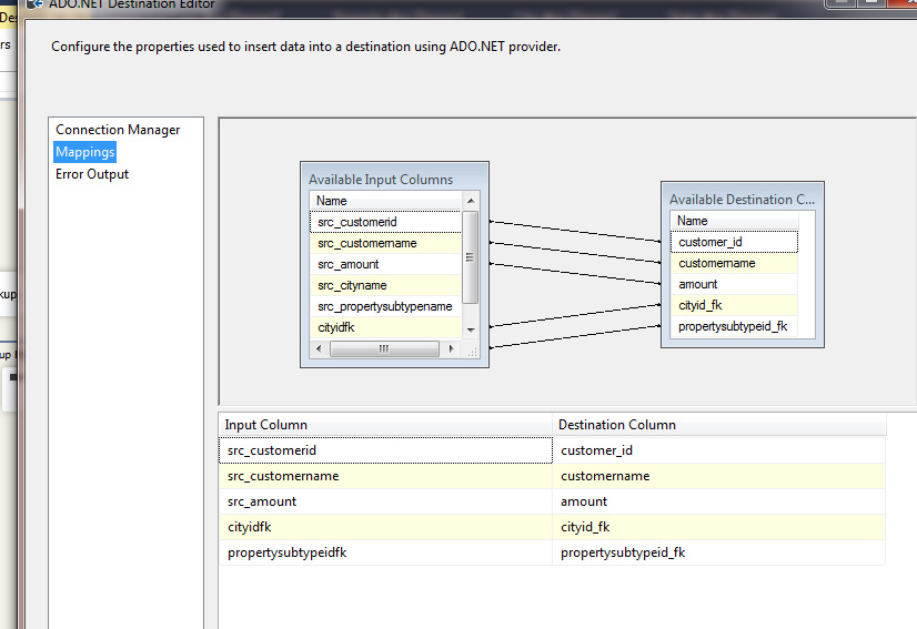
Once done save it
Step 9 :
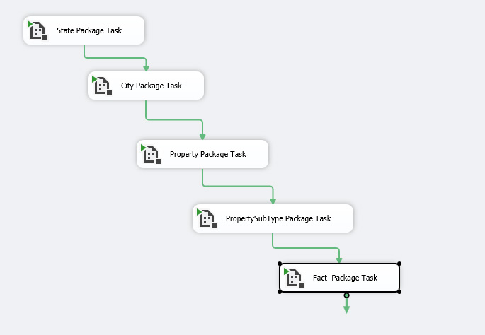
So now all our packages are ready to shoot so let's go to our main packagae and add one by one package using Executive package task component as shown in below image.
Step 10 :
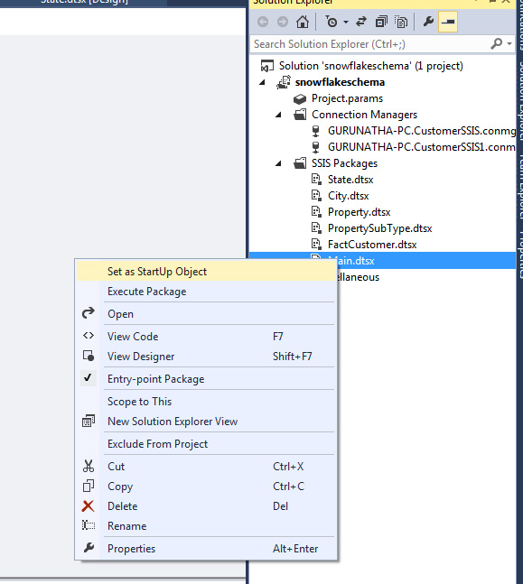
We are on to the final step of this article save everything, now to solution window select Main.dtsx package right click on it and make it as start up package.
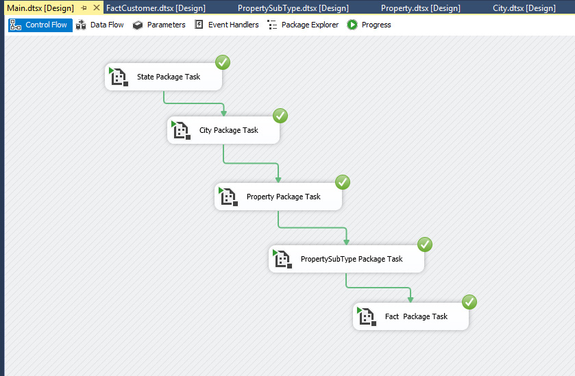
Finally we done almost just run the application by clicking on F5 button.
OUTPUT :
Friends, hope you have enjoyed this session in designing Snowflake schema model. If you have any doubts or queries feel free to get in touch with us. If you enjoyed and liked this article as useful please share it with your friends.
Order only MSBI self-study learning video materials which are available with customized package costing 999 INR/15$. Click this link here to see details and order it.